Chevrolet Trax: Rear wheel speed sensor replacement
Chevrolet Trax (2013-2022) Workshop Manual / Brakes / Antilock Brake System / Repair instructions / Rear wheel speed sensor replacement
Removal Procedure
WARNING: Refer to Brake Dust Warning .
- Raise and support the vehicle. Refer to Lifting and Jacking the Vehicle .
- Remove the tire and wheel assembly. Refer to Tire and Wheel Removal and Installation .
- Remove the rear wheelhouse panel liner. Refer to Rear Wheelhouse Liner Replacement .
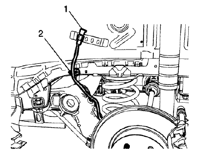
Fig. 34: Wheel Speed Sensor Electrical Connector
- Disconnect the wheel speed sensor electrical connector (1) and release the connector clip from the wheelhouse bracket.
- Release the wheel speed sensor harness clip (2) from the wheelhouse panel.
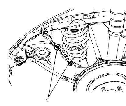
Fig. 35: Wheel Speed Sensor Harness Clips
- Release the wheel speed sensor harness clips (1) from the rear axle.
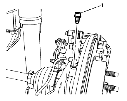
Fig. 36: Wheel Speed Sensor Bolt
- Remove the wheel speed sensor bolt (1).
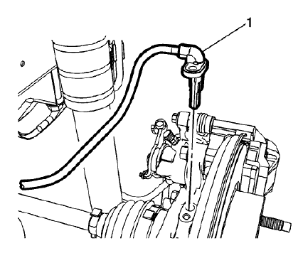
Fig. 37: Wheel Speed Sensor
- Remove the wheel speed sensor (1) from the rear suspension knuckle.
Installation Procedure
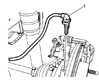
Fig. 38: Wheel Speed Sensor
- Install the wheel speed sensor (1) to the rear suspension knuckle.
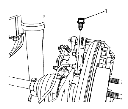
Fig. 39: Wheel Speed Sensor Bolt
CAUTION: Refer to Fastener Caution .
- Install the wheel speed sensor bolt (1) and tighten to 8 N.m (71 lb in).
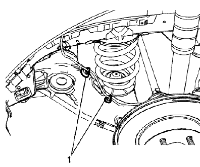
Fig. 40: Wheel Speed Sensor Harness Clips
- Install the wheel speed sensor harness clips (1) to the rear axle.
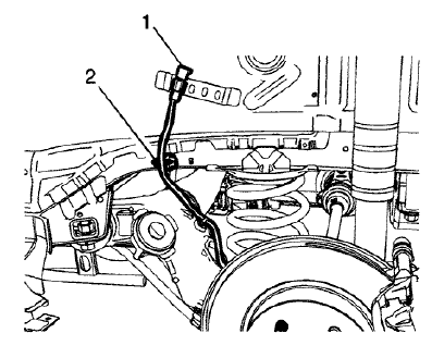
Fig. 41: Wheel Speed Sensor Electrical Connector
- Connect the wheel speed sensor electrical connector (1) and install the connector clip to the wheelhouse bracket.
- Install the wheel speed sensor harness clip (2) to the wheelhouse panel.
- Install the rear wheelhouse panel liner. Refer to Rear Wheelhouse Liner Replacement .
- Install the tire and wheel assembly. Refer to Tire and Wheel Removal and Installation .
- Perform the diagnostic system check. Refer to Diagnostic System Check - Vehicle .
READ NEXT:
 Vehicle stability control system switch replacement
Fig. 42: Vehicle Stability Control System Switch
Vehicle Stability Control System Switch Replacement
VEHICLE YAW SENSOR LEARN
The yaw rate sensor learn procedure can be completed with a scan tool
Description and operation
ABS DESCRIPTION AND OPERATION
Antilock Brake System Block Diagram
Fig. 45: Antilock Brake System Block Diagram
This vehicle is equipped with the MGH 60 Mando electronic stability control
brake
SEE MORE:
DTC P025A (Chassis control module)
Diagnostic Instructions
Perform the Diagnostic System Check - Vehicle prior to using this
diagnostic procedure.
Review Strategy Based Diagnosis for an overview of the diagnostic
approach.
Diagnostic Procedure Instructions provides an overview of each
diagnostic category.
DTC Descriptor
DT
Rear side door outer panel replacement
Special Tools
BO-6392 Flanging Tool Kit
BO-6396 Bonding Pliers
For equivalent regional tools, refer to Special Tools.
NOTE: According to different corrosion warranties, only the
regional mandatory joining
methods are allowed.
Removal Procedure
WARNING: Refer to Glass and Sheet Metal Handling Wa
© 2019-2026 Copyright www.chevtrax.com
