Chevrolet Trax: Rear side door outer panel replacement
Chevrolet Trax (2013-2022) Workshop Manual / Accessories & Equipment / Collision Repair / Collision repair - Repair instructions / Rear side door outer panel replacement
Special Tools
- BO-6392 Flanging Tool Kit
- BO-6396 Bonding Pliers
For equivalent regional tools, refer to Special Tools.
NOTE: According to different corrosion warranties, only the regional mandatory joining methods are allowed.
Removal Procedure
WARNING: Refer to Glass and Sheet Metal Handling Warning .
- Disable the SIR System. Refer to SIR Disabling and Enabling .
- Disconnect the negative battery cable. Refer to Battery Negative Cable Disconnection and Connection .
- Remove the rear side door. Refer to Rear Side Door Replacement .
- Remove the rear side door outside handle. Refer to Rear Side Door Outside Handle Replacement .
- Remove the sealers and anti-corrosion materials from the repair area, as necessary. Refer to Anti- Corrosion Treatment and Repair (Base)
.gif)
Fig. 89: Grinding Edges Of Rear Side Door Outer Panel
- Grind the edges of the rear side door outer panel (1) to separate the outer door panel from the door shell.
.gif)
Fig. 90: Rear Side Door Outer Door Panel
- Remove the rear side door outer door panel (1).
- Remove the sealers and anti-corrosion materials from the repair area, as necessary. Refer to Anti- Corrosion Treatment and Repair (Base) .
- Straighten the edges of the door shell.
Installation Procedure
- Align the rear side door outer panel.
- Verify the fit of the rear side door outer panel.
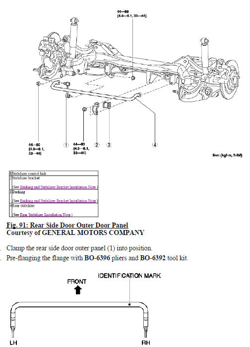
Fig. 92: Rear Side Door Outer Door Panel Hem Flanges
- Continue to hammer in stages along the hem flanges (1).
- Apply the sealers and anti-corrosion materials to the repair area, as necessary. Refer to Anti-Corrosion Treatment and Repair (Base) .
- Install the rear side door outside handle. Refer to Rear Side Door Outside Handle Replacement .
- Install the rear side door. Refer to Rear Side Door Replacement .
- Paint the repaired area. Refer to Basecoat/Clearcoat Paint Systems .
- Install all related panels and components.
- Connect the negative battery cable. Refer to Battery Negative Cable Disconnection and Connection .
- Enable the SIR system. Refer to SIR Disabling and Enabling
READ NEXT:
 Rear compartment floor panel replacement
Removal Procedure
WARNING: Refer to Approved Equipment for Collision Repair Warning .
WARNING: Refer to Glass and Sheet Metal Handling Warning .
Disable the SIR system. Refer to SIR Disabling and En
Rear wheelhouse outer panel replacement
Removal Procedure
WARNING: Refer to Approved Equipment for Collision Repair Warning .
WARNING: Refer to Glass and Sheet Metal Handling Warning
Disable the SIR system. Refer to SIR Disabling and Enab
Quarter outer panel sectioning
NOTE: According to different corrosion warranties, only the
regional mandatory joining
methods are allowed.
Removal Procedure
WARNING: Refer to Approved Equipment for Collision Repair Warning .
WARNI
SEE MORE:
Steering column replacement (CANADA, NJ1)
Removal Procedure
CAUTION:
With wheels of the vehicle facing straight ahead, secure the steering
wheel utilizing steering column anti-rotation pin, steering column
lock, or a strap to prevent rotation. Locking of the steering column
will prevent damage and a possible malfunction of the SIR system.
USB Port
The USB port is in the storage area
to the right of the infotainment
system. See Overview (Radio with
Touchscreen) on page 7-7 or
Overview (AM-FM Radio) on
page 7-3 or Overview (Radio with
CD/USB)
Portable devices are controlled by
using the menu system described in
Operation
Radio without Touchscre
© 2019-2026 Copyright www.chevtrax.com
