
Chevrolet Trax: Transmission mount bracket replacement -REAR (AWD)
Chevrolet Trax (2013-2022) Workshop Manual / Transmission / Automatic Transmission - 6T40 (MH8 MHB) / Repair instructions - on vehicle / Transmission mount bracket replacement -REAR (AWD)
Removal Procedure
- Remove the transfer case. Refer to Transfer Case Replacement .
.gif)
Fig. 43: Transmission Bracket Fasteners
- Remove and DISCARD the five transmission bracket fasteners (1, 2).
.gif)
Fig. 44: Transmission Bracket And Through Bolt
- Remove and DISCARD the rear transmission mount through bolt (1).
- Remove the transmission bracket (2) from the transmission.
Installation Procedure
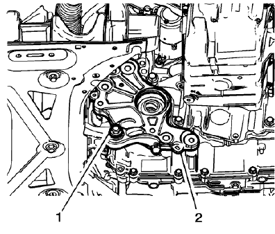
Fig. 45: Transmission Bracket And Through Bolt
- Install the transmission bracket (2) to the transmission.
- Install the NEW rear transmission through bolt (1). Do not tighten at this time.
.gif)
Fig. 46: Transmission Bracket Fasteners
CAUTION: Refer to Fastener Caution .
- Install the NEW transmission bracket to transmission fasteners (1) and tighten to 100 (74 lb ft) plus 30-40 degrees.
- Install the NEW transmission bracket to transmission fastener (2) and tighten to 60 (44 lb ft) plus 60-75 degrees.
.gif)
Fig. 47: Transmission Bracket And Through Bolt
- Install the NEW rear transmission mount through bolt (1) and tighten to 80 (59 lb ft) plus 45-60 degrees.
- Install the transfer case. Refer to Transfer Case Replacement
TRANSMISSION MOUNT BRACKET REPLACEMENT - REAR (FWD)
Removal Procedure
- Raise and support the vehicle. Refer to Lifting and Jacking the Vehicle .
- Remove the exhaust front pipe. Refer to Exhaust Front Pipe Replacement (LUV) , Exhaust Front Pipe Replacement .
- Using a suitable jack stand, support the rear of the transmission.
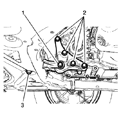
Fig. 48: Rear Transmission Mount Bracket To Rear Mount Through Bolt
- Remove and DISCARD the rear transmission mount bracket to rear mount through bolt (1).
.gif)
Fig. 49: Transmission Mount Bracket To Transmission Bolts
- Remove and DISCARD the 4 rear transmission mount bracket to transmission bolts (1).
- Remove the rear transmission mount bracket (2).
Installation Procedure
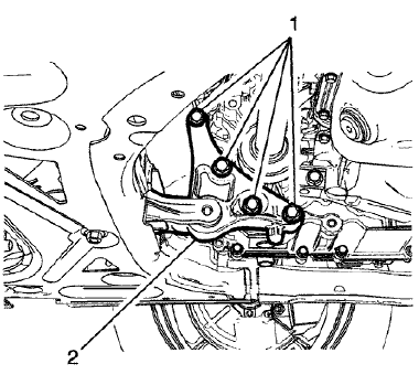
Fig. 50: Transmission Mount Bracket To Transmission Bolts
- Install the rear transmission mount bracket (2).
CAUTION: Refer to Fastener Caution .
- Install the 4 NEW rear transmission mount bracket to transmission bolts (1) and tighten to 100 (74 lb ft) plus 30-45 degrees.
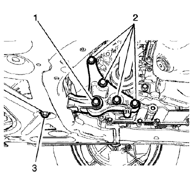
Fig. 51: Rear Transmission Mount Bracket To Rear Mount Through Bolt
- Install the NEW rear transmission mount bracket to rear mount through bolt (1) and tighten to 80 (59 lb ft) plus 45-60 degrees.
- Remove the jack stand.
- Install the exhaust front pipe. Refer to Exhaust Front Pipe Replacement (LUV) , Exhaust Front Pipe Replacement .
- Lower the vehicle.
READ NEXT:
 Transmission mount replacement - left side
Removal Procedure
Remove the battery tray. Refer to Battery Tray Replacement .
Fig. 52: Electronic Vacuum Pump (EVP)
Disconnect the electrical connector (1) from the Electronic Vacuum Pump
(E
Transmission replacement
Removal Procedure
Remove the battery tray. Refer to Battery Tray Replacement .
Remove the front bumper fascia opening upper cover. Refer to Front
Bumper Fascia Opening Upper
Cover Replacement .
Schematic wiring diagrams
Automatic transmission controls wiring schematics (ENCORE, MH8 OR MHB)
Module Power, Ground, Data Communication, and MIL
Fig. 1: Module Power, Ground, Data Communication, and MIL
Speed and Temperatu
SEE MORE:
Folding Seatback
The front passenger seatback may
fold flat.
Warning
If you fold the seatback forward to
carry longer objects, such as skis,
be sure any such cargo is not near an airbag. In a crash, an
inflating airbag might force that
object toward a person. This
could cause severe injury or even
death. Secure obje
Cupholders
If equipped, pull the rear seat
armrest down to access.
Sunglasses Storage
There may be sunglasses storage
over the driver door. Pull to open.
Underseat Storage
If equipped, there is storage under
the front passenger seat. Lift the
end of the tray up and pull it forward
to open. Push it in toward
© 2019-2026 Copyright www.chevtrax.com
