Chevrolet Trax: Front wheel drive shaft seal replacement - case side
.gif)
Fig. 17: View Of Case Side Front Wheel Drive Shaft Seal
Front Wheel Drive Shaft Seal Replacement - Case Side
.jpg)
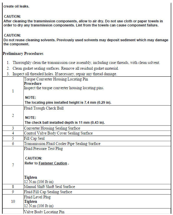
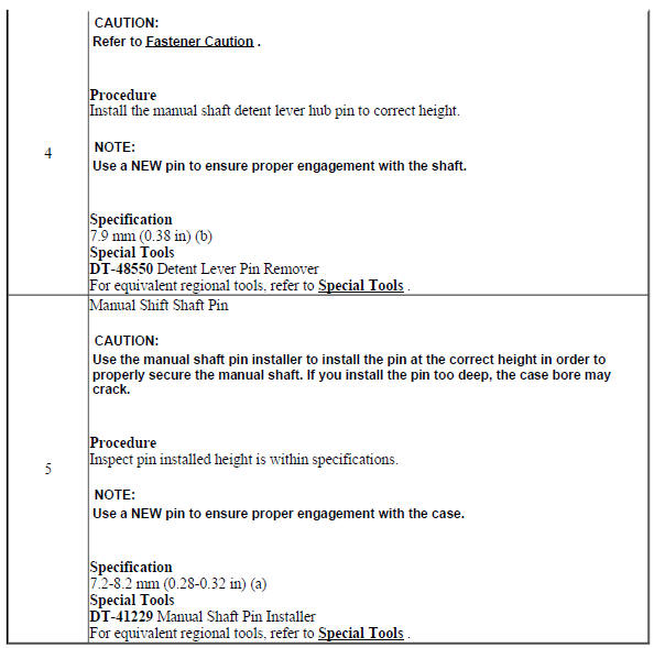
TRANSMISSION CASE CLEANING AND INSPECTION
.gif)
Fig. 18: Cleaning & Inspecting Transmission Case
Transmission Case Cleaning and Inspection
.jpg)
.jpg)
MANUAL SHIFT DETENT LEVER WITH SHAFT POSITION SWITCH ASSEMBLY AND PARK PAWL ACTUATOR INSTALLATION
Park Pawl Actuator Guide Installation
.gif)
Fig. 19: View Of Park Pawl Actuator Guide & Seal
Park Pawl Actuator Guide Installation
.jpg)
.jpg)
Park Pawl Actuator Installation
.gif)
Fig. 20: Identifying Manual Shift Detent Lever with Shaft Position Switch
Assembly & Park Pawl Actuator
Park Pawl Actuator Installation
.jpg)
MANUAL SHIFT SHAFT SEAL INSTALLATION
Fig. 21: Identifying Manual Shift Shaft Seal
Manual Shift Shaft Seal Installation
.jpg)
2-6 CLUTCH PISTON INSTALLATION (6T40)
.gif)
Fig. 22: View Of 2-6 Clutch Piston Assembly
2-6 Clutch Piston Installation (6T40)
.jpg)
.jpg)
LOW AND REVERSE AND 1-2-3-4 CLUTCH HOUSING, LOW AND REVERSE CLUTCH ASSEMBLY, OUTPUT SUN GEAR, AND 2-6 CLUTCH PLATE DISASSEMBLE (GEN 2)
.gif)
Fig. 23: 1-2-3-4 Clutch Housing And Clutch Assembly Components
Low and Reverse and 1-2-3-4 Clutch Housing, Low and Reverse Clutch Assembly, Output Sun Gear, and 2-6 Clutch Plate Disassemble (Gen 2)
.jpg)
.jpg)
READ NEXT:
 Input, reaction, and output carrier disassemble
Fig. 24: Disassembled View Of Input, Reaction & Output Carrier
Courtesy of GENERAL MOTORS COMPANY
Input, Reaction, and Output Carrier Disassemble
3-5-REVERSE AND 4-5-6 CLUTCH HOUSING DISASSEMB
Low and reverse and 1-2-3-4 clutch housing isassemble
Low and Reverse Clutch Piston Removal
Fig. 39: View Of Low & Reverse Clutch Piston
Low and Reverse Clutch Piston Removal
1-2-3-4 Clutch Piston Removal
Fig. 40: View Of 1-2-3-4 Clutch Pisto
Drive sprocket, driven sprocket, and drive link cleaning and inspection
Fig. 45: View Of Drive Sprocket, Driven Sprocket & Drive Link
Drive Sprocket, Driven Sprocket, and Drive Link Cleaning and Inspection
DRIVE AND DRIVEN SPROCKET, DRIVE LINK, AND PARK PAWL INSTA
SEE MORE:
DTC U0078: Control module communication low speed can bus off
Diagnostic Instructions
Perform the Diagnostic System Check - Vehicle prior to using this
diagnostic procedure.
Review Strategy Based Diagnosis for an overview of the diagnostic
approach.
Diagnostic Procedure Instructions provides an overview of each
diagnostic category.
DTC Descriptor
DT
DTC B3933: Air conditioning evaporator temperature sensor
Diagnostic Instructions
Perform the Diagnostic System Check - Vehicle prior to using this
diagnostic procedure.
Review Strategy Based Diagnosis for an overview of the diagnostic
approach.
Diagnostic Procedure Instructions provides an overview of each
diagnostic category.
DTC Descriptors
D
