
Chevrolet Trax: Front brake shield replacement
Chevrolet Trax (2013-2022) Workshop Manual / Brakes / Disc Brakes / Repair instructions / Front brake shield replacement
Removal Procedure
WARNING: Refer to Brake Dust Warning .
- Raise and support the vehicle. Refer to Lifting and Jacking the Vehicle .
- Remove the front tire and wheel assembly. Refer to Tire and Wheel Removal and Installation .
- Remove the front brake rotor. Refer to Front Brake Rotor Replacement.
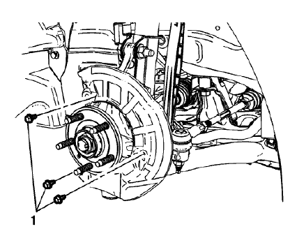
Fig. 72: Front Brake Shield Bolts
- Remove the front brake shield bolts (1).
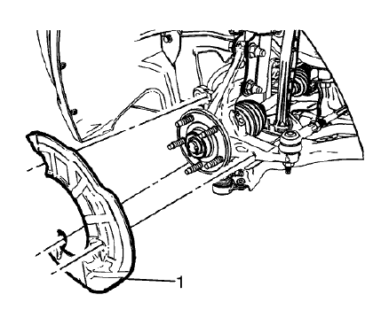
Fig. 73: Front Brake Shield
- Remove the front brake shield (1).
Installation Procedure
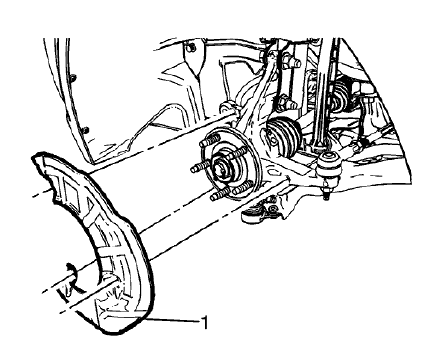
Fig. 74: Front Brake Shield
- Install the front brake shield (1).
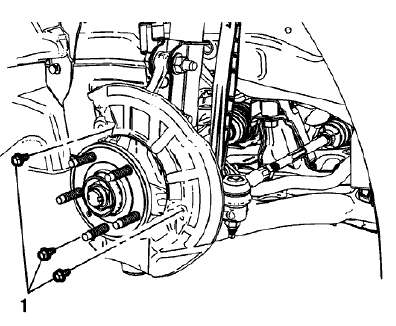
Fig. 75: Front Brake Shield Bolts
CAUTION: Refer to Fastener Caution .
- Install the front brake shield bolts (1) and tighten to 9 N.m (80 lb in).
- Install the front brake rotor. Refer to Front Brake Rotor Replacement.
- Install the tire and wheel assembly. Refer to Tire and Wheel Removal and Installation .
REAR BRAKE SHIELD REPLACEMENT
Removal Procedure
WARNING: Refer to Brake Dust Warning .
- Raise and support the vehicle. Refer to Lifting and Jacking the Vehicle .
- Remove the rear tire and wheel assembly. Refer to Tire and Wheel Removal and Installation .
- Remove the rear brake rotor. Refer to Rear Brake Rotor Replacement.
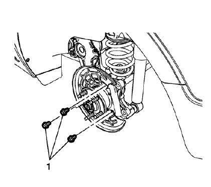
Fig. 76: Rear Brake Shield Bolts
- Remove the rear brake shield bolts (1).
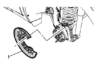
Fig. 77: Rear Brake Shield
- Remove the rear brake shield (1).
Installation Procedure
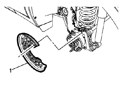
Fig. 78: Rear Brake Shield
- Install the rear brake shield (1).
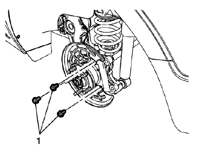
Fig. 79: Rear Brake Shield Bolts
CAUTION: Refer to Fastener Caution
- Install the rear brake shield bolts (1) and tighten to 9 N.m (80 lb in).
- Install the rear brake rotor. Refer to Rear Brake Rotor Replacement.
- Install the rear tire and wheel assembly. Refer to Tire and Wheel Removal and Installation .
READ NEXT:
 Brake rotor assembled lateral runout correction
NOTE:
Brake rotor thickness variation MUST be checked BEFORE checking for
assembled lateral runout (LRO). Thickness variation exceeding the
maximum acceptable level can cause brake pulsation. Refe
Brake rotor assembled lateral runout correction - on vehicle lathe
Special Tools
CH-45101-100 Conical Brake Rotor Washers
For equivalent regional tools, refer to Special Tools.
WARNING: Refer to Brake Dust Warning .
Fig. 80: One Lug Nut & Conical Brake Rotor Wa
Description and operation
DISC BRAKE SYSTEM DESCRIPTION AND OPERATION
System Component Description
The disc brake system consists of the following components
Disc Brake Pads
Applies mechanical output force from the hydraulic b
SEE MORE:
Radio controls malfunction (monochrome display)
Diagnostic Instructions
Perform the Diagnostic System Check - Vehicle prior to using this
diagnostic procedure.
Review Strategy Based Diagnosis for an overview of the diagnostic
approach.
Diagnostic Procedure Instructions provides an overview of each
diagnostic category.
Diagnostic Fault
Oil pan replacement
Special Tools
EN-49980 Guidance Pins
For equivalent regional tools, refer to Special Tools.
Removal Procedure
Remove the right front wheelhouse liner. Refer to Front Wheelhouse Liner
Replacement (Trax) ,
Front Wheelhouse Liner Replacement (Encore) .
Remove the oil filter and drain the engine o
© 2019-2026 Copyright www.chevtrax.com
