Chevrolet Trax: Description and operation
DISC BRAKE SYSTEM DESCRIPTION AND OPERATION
System Component Description
The disc brake system consists of the following components
Disc Brake Pads
Applies mechanical output force from the hydraulic brake calipers to friction surfaces of brake rotors.
Disc Brake Rotors
Uses mechanical output force applied to friction surfaces from the disc brake pads to slow speed of tire and wheel assembly rotation
Disc Brake Pad Hardware
Secures disc brake pads firmly in proper relationship to the hydraulic brake calipers. Enables a sliding motion of brake pads when mechanical output force is applied.
Disc Brake Caliper Hardware
Provides mounting for hydraulic brake caliper and secures the caliper firmly in proper relationship to caliper bracket. Enables a sliding motion of the brake caliper to the brake pads when mechanical output force is applied.
System Operation
Mechanical output force is applied from the hydraulic brake caliper pistons to the inner brake pads. As the pistons press the inner brake pads outward, the caliper housings draw the outer brake pads inward. This allows the output force to be equally distributed. The brake pads apply the output force to the friction surfaces on both sides of the brake rotors, which slows the rotation of the tire and wheel assemblies. The correct function of both the brake pad and brake caliper hardware is essential for even distribution of braking force.
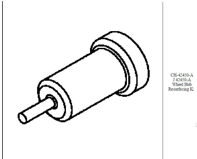
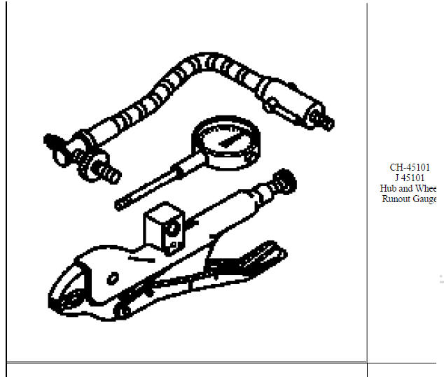
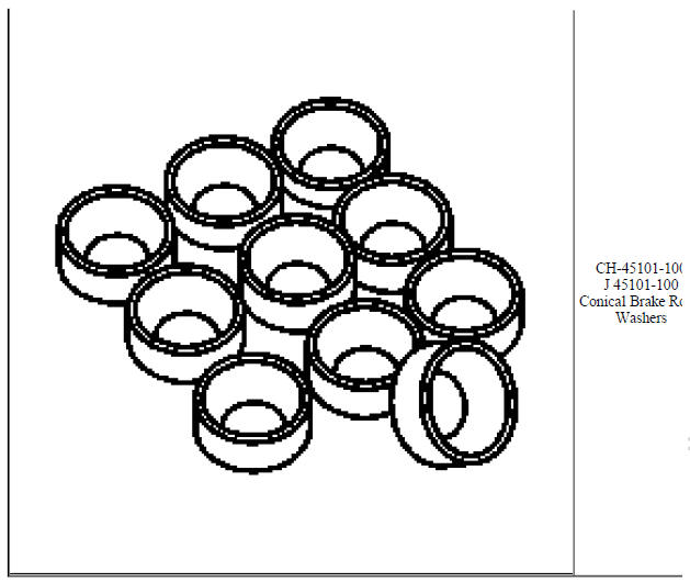
SPECIAL TOOLS AND EQUIPMENT
SPECIAL TOOLS
READ NEXT:
 Brake drum diameter measurement
SPECIFICATIONS
FASTENER TIGHTENING SPECIFICATIONS
Fastener Tightening Specifications
DRUM BRAKE COMPONENT SPECIFICATIONS
Drum Brake Component Specifications
DIAGNOSTIC INFORMATION AND PROCEDURES
B
SEE MORE:
DTC B3881 OR B3882
Diagnostic Instructions
Perform the Diagnostic System Check - Vehicle prior to using this
diagnostic procedure.
Review Strategy Based Diagnosis for an overview of the diagnostic
approach.
Diagnostic Procedure Instructions provides an overview of each
diagnostic category
DTC Descriptors
DT
Control solenoid valve and transmission control module assembly input Shaft
speed/output shaft speed input test
Special Tools
EL 35616 GM-Approved Terminal Test Kit
EL 38522 Variable Signal Generator
For equivalent regional tools, refer to Special Tools .
Fig. 2: View Of Special Tool & Control Solenoid Valve and Transmission
Control Module Assembly
The purpose of this test is to provide a simulated
