
Chevrolet Trax: Schematic wiring diagrams
SPECIFICATIONS
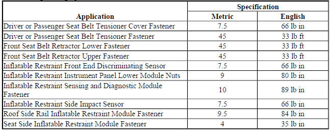
Fastener Tightening Specifications
SCHEMATIC WIRING DIAGRAMS
SIR WIRING SCHEMATICS (ENCORE)
Power, Ground, Passenger Presence, Serial Data and Indicators
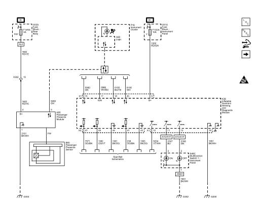
Fig. 1: Power, Ground, Passenger Presence, Serial Data and Indicators
Front Air Bags, and Impact Sensors (AY0 or AYF)
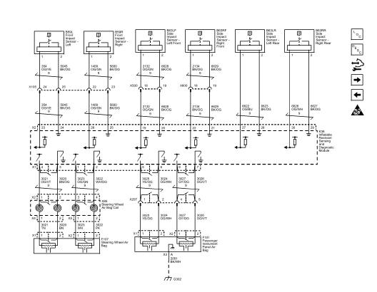
Fig. 2: Front Air Bags, and Impact Sensors (AY0 or AYF)
Front Air Bags, and Sensors (AJG or AYC)
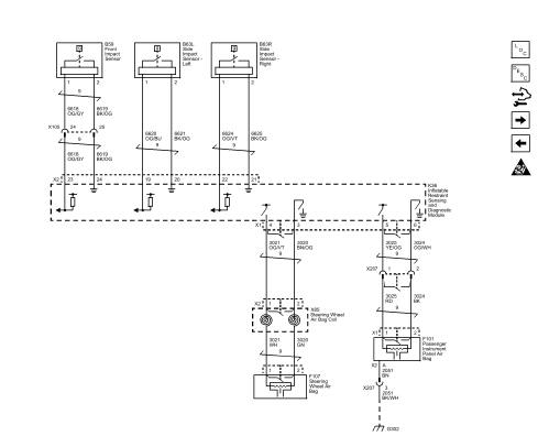
Fig. 3: Front Air Bags, and Sensors (AJG or AYC)
Seat, Knee, and Roof Air Bags
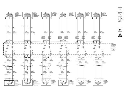
Fig. 4: Seat, Knee, and Roof Air Bags
SIR WIRING SCHEMATICS (TRAX)
Power, Ground, Passenger Presence, Disable Switch, Serial Data and Indicators
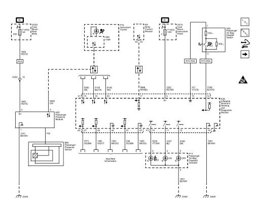
Fig. 5: Power, Ground, Passenger Presence, Disable Switch, Serial Data and
Indicators
Front Air Bags, and Front Impact Sensors (AYC)
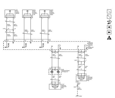
Fig. 6: Front Air Bags, and Front Impact Sensors (AYC)
Front Air Bags, and Impact Sensors (AY0 or AYF)
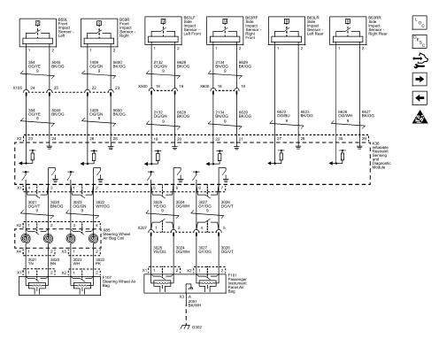
Fig. 7: Front Air Bags, and Impact Sensors (AY0 or AYF)
Pretensioners and Seat, Knee, and Roof Air Bags
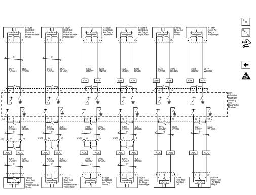
Fig. 8: Pretensioners and Seat, Knee, and Roof Air Bags
COMPONENT LOCATOR
SIR IDENTIFICATION VIEWS (NON-NORTH AMERICA)
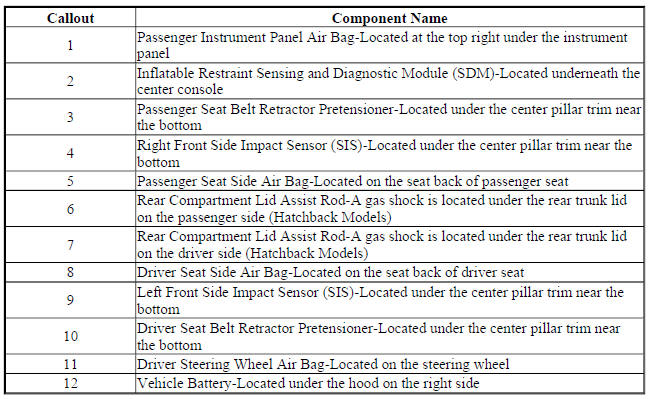
The SIR Identification Views shown below illustrate the approximate location of all SIR components available for the vehicle. This will assist in determining the appropriate SIR Disabling and Enabling for a given service procedure, refer to SIR Disabling and Enabling.
Non-North American Models
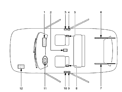
Fig. 9: Except North American Models
-
Passenger Instrument Panel Air Bag-Located at the top right under the instrument
panel -
Inflatable Restraint Sensing and Diagnostic Module (SDM)-Located underneath the
center console -
Passenger Seat Belt Retractor Pretensioner-Located under the center pillar trim near
the bottom -
Right Front Side Impact Sensor (SIS)-Located under the center pillar trim near the
bottom -
Passenger Seat Side Air Bag-Located on the seat back of passenger seat
-
Rear Compartment Lid Assist Rod-A gas shock is located under the rear trunk lid
on the passenger side (Hatchback Models) -
Rear Compartment Lid Assist Rod-A gas shock is located under the rear trunk lid
on the driver side (Hatchback Models) -
Driver Seat Side Air Bag-Located on the seat back of driver seat
-
Left Front Side Impact Sensor (SIS)-Located under the center pillar trim near the
bottom -
Driver Seat Belt Retractor Pretensioner-Located under the center pillar trim near
the bottom -
Driver Steering Wheel Air Bag-Located on the steering wheel
-
Vehicle Battery-Located under the hood on the right side
READ NEXT:
 DTC B0012 OR B0013: Driver steering wheel air bag deployment loop
DIAGNOSTIC CODE INDEX
DTC B0012 OR B0013: DRIVER STEERING WHEEL AIR BAG DEPLOYMENT LOOP
Diagnostic Instructions
Perform the Diagnostic System Check - Vehicle prior to using this
diagnost
DTC B0014, B0021, B0031, OR B0038: Seat side air bag deployment loop
Diagnostic Instructions
Perform the Diagnostic System Check - Vehicle prior to using this
diagnostic procedure.
Review Strategy Based Diagnosis for an overview of the diagnostic
approach.
Diag
SEE MORE:
Camshaft timing chain installation
Special Tools
EN-952 Fixing Pin
EN-953-A Fixing Tool
EN-955-10 Fixing Pin from EN-955 Kit
For equivalent regional tools, refer to Special Tools.
The engine should be adjusted to TDC.
The crankshaft should be locked with EN-952 fixing pin.
The camshaft should be locked with EN-953-A fixing t
Symptoms - data communications
NOTE: The following steps must be completed before using the
symptom tables.
Perform the Diagnostic System Check - Vehicle before using the symptom
tables in order to verify that
all of the following are true:
There are no Diagnostic Trouble Codes (DTC) set.
The devices can communicate via
