Chevrolet Trax: Schematic wiring diagrams
Chevrolet Trax (2013-2022) Workshop Manual / Brakes / Antilock Brake System / Schematic wiring diagrams
SPECIFICATIONS
FASTENER TIGHTENING SPECIFICATIONS
Fastener Tightening Specifications
.jpg)
SCHEMATIC WIRING DIAGRAMS
ANTILOCK BRAKE SYSTEM WIRING SCHEMATICS (ENCORE)
Module Power, Ground and Subsystem References
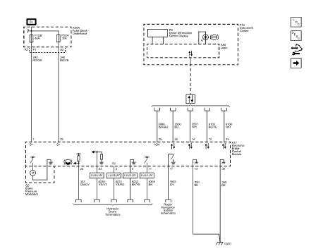
Fig. 1: Module Power, Ground and Subsystem References
Wheel Speed Sensors
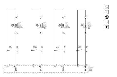
Fig. 2: Wheel Speed Sensors
Stability Control
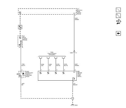
Fig. 3: Stability Control
ANTILOCK BRAKE SYSTEM WIRING SCHEMATICS (TRAX)
Module Power, Ground and Subsystem References
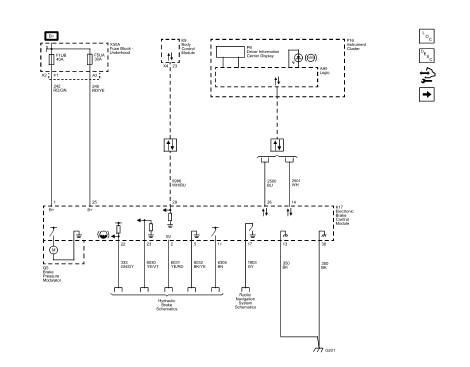
Fig. 4: Module Power, Ground and Subsystem References
Wheel Speed Sensors
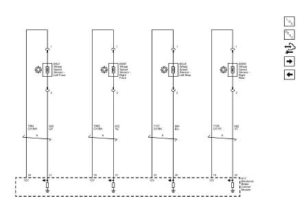
Fig. 5: Wheel Speed Sensors
Stability Control
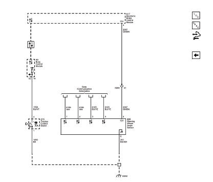
Fig. 6: Stability Control
READ NEXT:
 DTC B2745 (WITH C67/CJ2): Traction control switch
DIAGNOSTIC CODE INDEX
DTC B2745 (WITH C67/CJ2): Traction control switch
Diagnostic Instructions
Perform the Diagnostic System Check - Vehicle prior to using this
diagnostic procedure.
Revie
DTC B2745 (WITH C60/C41): Traction control switch
Diagnostic Instructions
Perform the Diagnostic System Check - Vehicle prior to using this
diagnostic procedure.
Review Strategy Based Diagnosis for an overview of the diagnostic
approach.
Diag
SEE MORE:
Vehicle Data
Capacities and Specifications
The following approximate capacities are given in metric and English
conversions. See Recommended Fluids and
Lubricants for more information.
Engine Specifications
Engine Drive Belt Routing
1.4L L4 Engine
1.8L L4 Engine (with Air Conditioning)
1.8L L4 Engine
Trouble Shooting
NOTE: This article is generic in nature and all information
does not apply to all
vehicles. For vehicle specific information, see the appropriate articles in the
ENGINE PERFORMANCE category.
ENGINE PERFORMANCE
NOTE: This article is generic in nature and all information does
not apply to all
vehicl
© 2019-2026 Copyright www.chevtrax.com
