Chevrolet Trax: Schematic wiring diagrams
ENGINE CONTROLS WIRING SCHEMATICS (ENCORE)
Module Power, Ground, Serial Data, and MIL
.jpg)
Fig. 1: Module Power, Ground, Serial Data, and MIL
5V1, 5V2, and Low Reference Bus (1 of 2)
.jpg)
Fig. 2: 5V1, 5V2, and Low Reference Bus (1 of 2)
5V3, 5V4, and Low Reference Bus (2 of 2)
.jpg)
Fig. 3: 5V3, 5V4, and Low Reference Bus (2 of 2)
Engine Data Sensors - Pressure, and Temperature
.jpg)
Fig. 4: Engine Data Sensors - Pressure, and Temperature
Camshaft, Crankshaft, and Knock Sensors, Camshaft Actuators
.jpg)
Fig. 5: Camshaft, Crankshaft, and Knock Sensors, Camshaft Actuators
Engine Data Sensors - Throttle and Brake Sensor Controls
.jpg)
Fig. 6: Engine Data Sensors - Throttle and Brake Sensor Controls
Fuel Controls - Fuel Injectors and Ignition Controls
.jpg)
Fig. 7: Fuel Controls - Fuel Injectors and Ignition Controls
Engine Data Sensors - Oxygen Sensors
.jpg)
Fig. 8: Engine Data Sensors - Oxygen Sensors
Fuel Controls - Evaporative Emission and Device Controls
.jpg)
Fig. 9: Fuel Controls - Evaporative Emission and Device Controls
Fuel Controls - Fuel Pump and Fuel Pump Controls (LUV)
.jpg)
Fig. 10: Fuel Controls - Fuel Pump and Fuel Pump Controls (LUV)
Fuel Controls - Fuel Pump (LUJ)
.jpg)
Fig. 11: Fuel Controls - Fuel Pump (LUJ)
Controlled/Monitored Subsystem References
.jpg)
Fig. 12: Controlled/Monitored Subsystem References
ENGINE CONTROLS WIRING SCHEMATICS (TRAX)
Module Power, Ground, Serial Data, and MIL
.jpg)
Fig. 13: Module Power, Ground, Serial Data, and MIL
5V1, 5V2, and Low Reference Bus (1 of 2)
.jpg)
Fig. 14: 5V1, 5V2, and Low Reference Bus (1 of 2)
5V3, 5V4, and Low Reference Bus (2 of 2)
.jpg)
Fig. 15: 5V3, 5V4, and Low Reference Bus (2 of 2)
Engine Data Sensors - Pressure, and Temperature
.jpg)
Fig. 16: Engine Data Sensors - Pressure, and Temperature
Camshaft, Crankshaft, and Knock Sensors, Camshaft Actuators
.jpg)
Fig. 17: Camshaft, Crankshaft, and Knock Sensors, Camshaft Actuators
Engine Data Sensors - Throttle and Brake Sensor Controls
.jpg)
Fig. 18: Engine Data Sensors - Throttle and Brake Sensor Controls
Fuel Controls - Fuel Injectors and Ignition Controls
.jpg)
Fig. 19: Fuel Controls - Fuel Injectors and Ignition Controls
Engine Data Sensors - Oxygen Sensors
.jpg)
Fig. 20: Engine Data Sensors - Oxygen Sensors
Fuel Controls - Evaporative Emission and Device Controls
.jpg)
Fig. 21: Fuel Controls - Evaporative Emission and Device Controls
Fuel Controls - Fuel Pump and Fuel Pump Controls (FHA)
.jpg)
Fig. 22: Fuel Controls - Fuel Pump and Fuel Pump Controls (FHA)
Fuel Controls - Fuel Pump (-FHA)
.jpg)
Fig. 23: Fuel Controls - Fuel Pump (-FHA)
Controlled/Monitored Subsystem References
.jpg)
Fig. 24: Controlled/Monitored Subsystem References
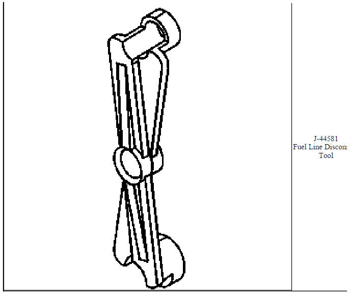
SPECIAL TOOLS AND EQUIPMENT
SPECIAL TOOLS (DIAGNOSTIC TOOLS)
.jpg)
.jpg)
.jpg)
.jpg)
.jpg)
.jpg)
.jpg)
.jpg)

.jpg)
.jpg)
.jpg)
.jpg)
.jpg)
.jpg)
.jpg)
.jpg)
.jpg)
.jpg)
.jpg)
.jpg)
.jpg)
.jpg)
.jpg)
.jpg)
.jpg)
.jpg)
.jpg)
.jpg)
.jpg)
.jpg)
.jpg)
.jpg)
.jpg)
.jpg)
.jpg)
.jpg)
.jpg)
.jpg)
.jpg)
.jpg)
.jpg)
SPECIFICATIONS
Temperature Versus Resistance
.jpg)
Temperature Versus Resistance - Intake Air Temperature Sensor (Bosch Sensor)
.jpg)
.jpg)
Temperature Versus Resistance - Intake Air Temperature Sensor (Delco Sensor)
.jpg)
Altitude Versus Barometric Pressure
.jpg)
.jpg)
Ignition System Specifications
.jpg)
Fastener Tightening Specifications
.jpg)
.jpg)
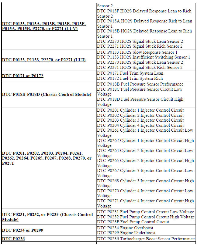
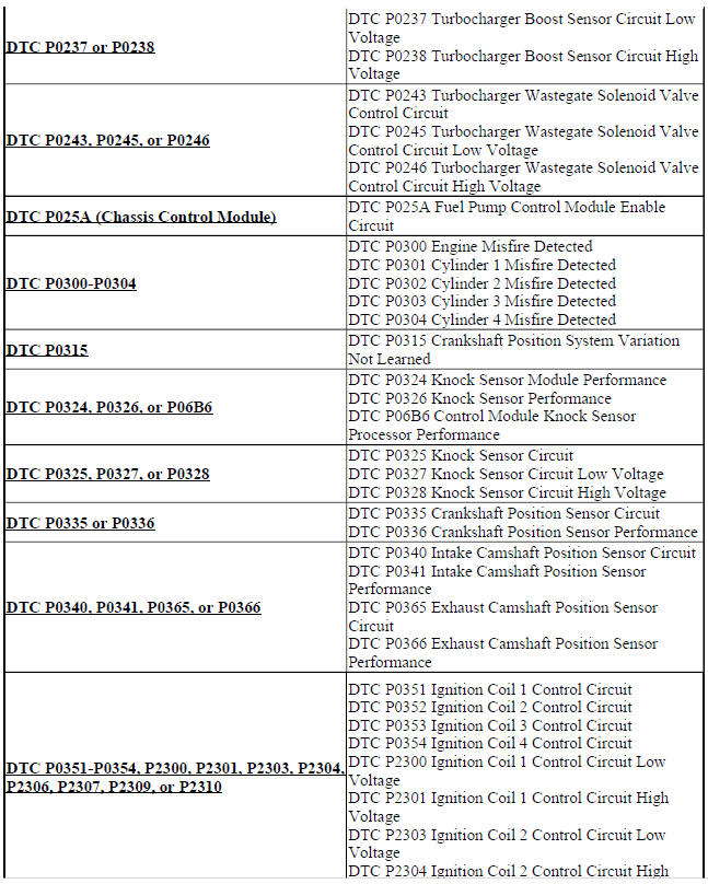
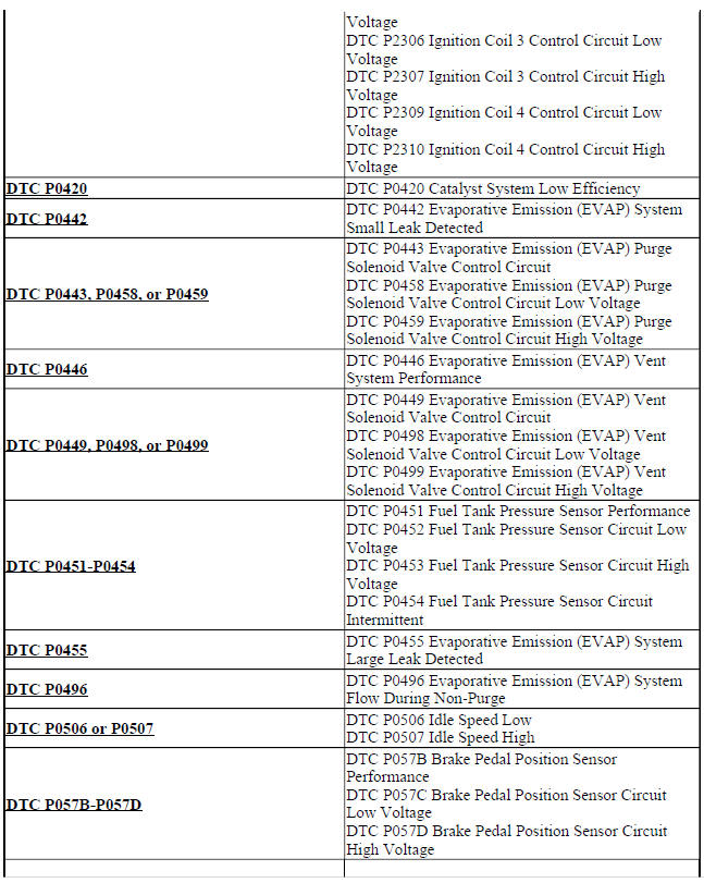
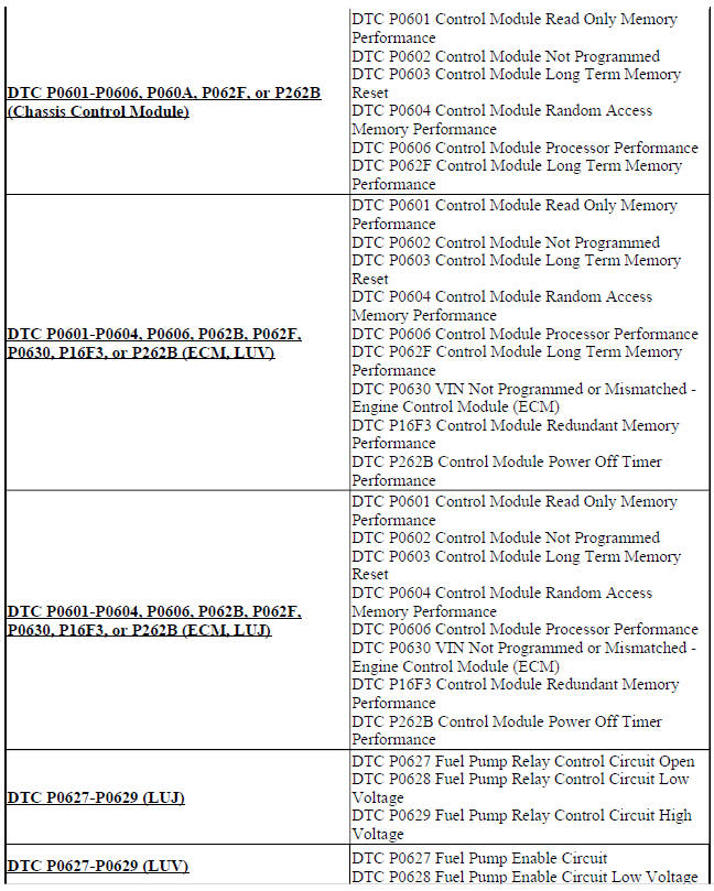
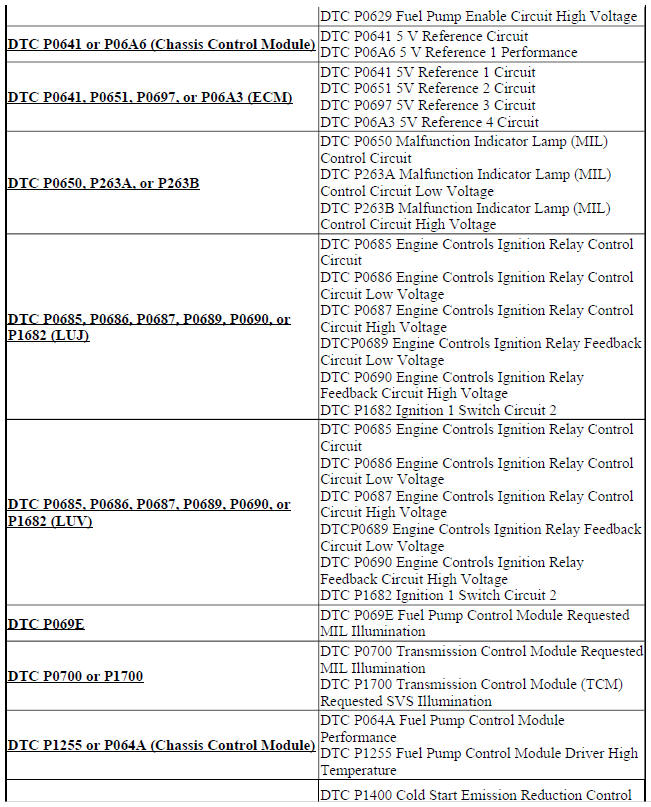
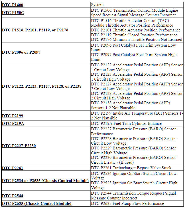
DIAGNOSTIC CODE INDEX
.jpg)
.jpg)
.jpg)
READ NEXT:
 Schematic wiring diagrams
SPECIFICATIONS
TEMPERATURE VERSUS RESISTANCE
Temperature Versus Resistance
Fastener Tightening Specifications
SCHEMATIC WIRING DIAGRAMS
ENGINE HEATING/COOLING WIRING SCHEMATICS (ENCORE)
Engine C
SEE MORE:
Cooling fan inoperative (LUJ OR LUV)
Diagnostic Instructions
Perform the Diagnostic System Check - Vehicle prior to using this
diagnostic procedure.
Review Strategy Based Diagnosis for an overview of the diagnostic
approach.
Diagnostic Procedure Instructions provides an overview of each
diagnostic category.
Circuit/System De
Onstar call center remote function requests malfunction
Diagnostic Instructions
Perform the Diagnostic System Check - Vehicle prior to using this
diagnostic procedure.
Review Strategy Based Diagnosis for an overview of the diagnostic
approach.
Diagnostic Procedure Instructions provides an overview of each
diagnostic category.
Circuit/System De
