Chevrolet Trax: Repair instructions - on vehicle
DRIVE BELT REPLACEMENT
Special Tools
- EN-48488 Holding Wrench
- EN-955 Locking Pin
For equivalent regional tools, refer to Special Tools.
Removal Procedure
- Remove the right front wheelhouse liner. Refer to Front Wheelhouse Liner Replacement (Trax) , Front Wheelhouse Liner Replacement (Encore) .
- Install the engine support fixture. Refer to Engine Support Fixture.
- Remove the engine mount. Refer to Engine Mount Replacement - Right Side
.gif)
Fig. 16: Holding Wrench And Drive Belt Tensioner
Courtesy of GENERAL MOTORS COMPANY
- Install EN-48488 holding wrench (2) to the drive belt tensioner (1).
.gif)
Fig. 17: Locking Pin
- Move the drive belt tensioner clockwise until the drive belt tensioner can be fixed with EN-955 locking pin (1).
- Remove the EN-48488 holding wrench.
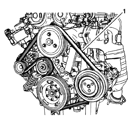
Fig. 18: Drive Belt Routing
- Remove the drive belt (1).
Installation Procedure
.gif)
Fig. 19: Drive Belt Routing
- Install the drive belt (1).
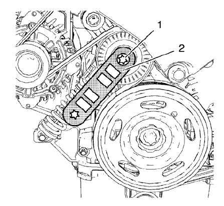
Fig. 20: Holding Wrench And Drive Belt Tensioner
- Install the EN-48488 holding wrench (2) to the drive belt tensioner (1).
.gif)
Fig. 21: Locking Pin
- Move the drive belt tensioner clockwise until EN-955 locking pin (1) can be removed.
- Allow the tensioner to slide back slowly.
- Remove the EN-48488 holding wrench.
- Install the right front wheelhouse liner. Refer to Front Wheelhouse Liner Replacement (Trax) , Front Wheelhouse Liner Replacement (Encore)
- Install the engine mount. Refer to Engine Mount Replacement - Right Side.
- Remove the engine support fixture. Refer to Engine Support Fixture.
DRIVE BELT TENSIONER REPLACEMENT
Special Tools
- EN-955 Locking Pin
- EN-48488 Holding Wrench
For equivalent regional tools, refer to Special Tools.
Removal Procedure
- Remove the drive belt. Refer to Drive Belt Replacement.
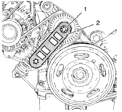
Fig. 22: Holding Wrench And Drive Belt Tensioner
- Install the EN-48488 holding wrench (2) to the drive belt tensioner (1).
.gif)
Fig. 23: Locking Pin
- Move the drive belt tensioner clockwise until the drive belt tensioner can be fixed with EN-955 locking pin (1).
- Remove the EN-48488 holding wrench.
- Remove the drive belt.
- Repeat steps 4 and 5 in order to remove the EN-955 locking pin from the drive belt tensioner.
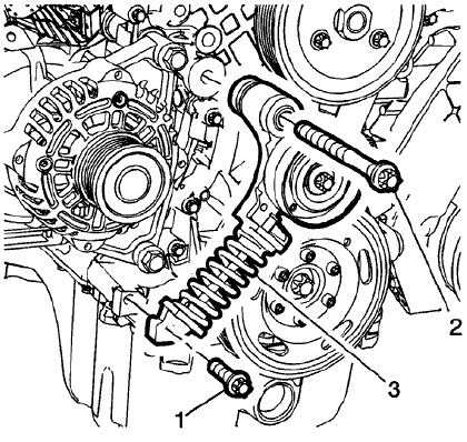
Fig. 24: Drive Belt Tensioner And Bolts
- Remove the lower drive belt tensioner bolt (1).
- Remove the upper drive belt tensioner bolt (2).
- Remove the drive belt tensioner (3).
Installation Procedure
.gif)
Fig. 25: Drive Belt Tensioner And Bolts
- Install the drive belt tensioner (3).
- Install the lower drive belt tensioner bolt (1).
- Install the upper drive belt tensioner bolt (2).
CAUTION: Refer to Fastener Caution .
- Tighten the lower drive belt tensioner bolt (1) to 22 N.m (16 lb ft).
- Tighten the upper drive belt tensioner bolt (2) to 55 N.m (41 lb ft).
.gif)
Fig. 26: Holding Wrench And Drive Belt Tensioner
NOTE: Engine mount bracket is removed
- Install the EN-48488 holding wrench (2) to drive belt tensioner (1).
.gif)
Fig. 27: Locking Pin
- Move the drive belt tensioner clockwise until the drive belt tensioner can be fixed with EN-955 locking pin (1).
- Install the drive belt.
- Move the drive belt tensioner clockwise until EN-955 locking pin can be removed.
- Allow the tensioner to slide back slowly.
- Remove the EN-48488 holding wrench.
- Install the drive belt. Refer to Drive Belt Replacement.
ENGINE MOUNT REPLACEMENT - RIGHT SIDE
.gif)
Fig. 28: Engine Mount - Right Side
Engine Mount Replacement - Right Side
.jpg)
ENGINE MOUNT BRACKET REPLACEMENT - RIGHT SIDE
.gif)
Fig. 29: Engine Mount Bracket - Right Side
Engine Mount Bracket Replacement - Right Side
.jpg)
.jpg)
ENGINE COVER REPLACEMENT
.gif)
Fig. 30: Engine Cover And Oil Cap
Courtesy of GENERAL MOTORS COMPANY
Engine Cover Replacement
.jpg)
READ NEXT:
 Intake manifold replacement - Removal Procedure
Disconnect the battery negative cable. Refer to Battery Negative Cable
Disconnection and
Connection .
Remove the engine cover. Refer to Engine Cover Replacement.
Raise and support the vehicle.
Intake manifold replacement - Installation Procedure
Clean the sealing surfaces.
Fig. 38: Intake Manifold
Install the intake manifold (1) along with a NEW intake manifold gasket.
Fig. 39: Intake Manifold Bolts
CAUTION: Refer to Fastener Cautio
SEE MORE:
Power seats system description and operation
The power seat system consists of the following components:
Seat adjuster switch
Seat horizontal motor
Seat front vertical motor
Seat rear vertical motor
NOTE: If equipped, the passenger seat block diagram is
identical to the driver seat.
Power Seat Block Diagram
Fig. 14: Power Seat Block D
DTC P00EA-P00EC
Diagnostic Instructions
Perform the Diagnostic System Check - Vehicle prior to using this
diagnostic procedure.
Review Strategy Based Diagnosis for an overview of the diagnostic
approach.
Diagnostic Procedure Instructions provides an overview of each
diagnostic category.
DTC Descriptors
D
